Difference between revisions of "RF Cheater"
| (17 intermediate revisions by the same user not shown) | |||
| Line 2: | Line 2: | ||
== Introduction == | == Introduction == | ||
| − | The RF Cheater Board is a simple breakout board for the ([https://www.nordicsemi.com/kor/Products/2.4GHz-RF/nRF24L01P NRF24L01+ 2.4GHz Transceiver Module]) and ([ | + | The RF Cheater Board is a simple breakout board for the ([https://www.nordicsemi.com/kor/Products/2.4GHz-RF/nRF24L01P NRF24L01+ 2.4GHz Transceiver Module]) and ([http://www.esp8266.com ESP8266 WiFi Module]). The board was designed to plug right on top of the [[Cheater_Board | Cheater Board]] |
| − | [[File:RFCheater.png| | + | Features of the board: |
| + | * Supports the low cost WiFi module ESP-01. Search for ESP-01 in eBay or Amazon. I have seen these go for as low as $3USD | ||
| + | * Supports the NRF24L01+ 2.4GHz Wireless Transceiver. Great for point-point or local mesh networks. See pictures below for reference to which module is supported. | ||
| + | * Interface pins for both NRF24L01+ and ESP8266 routed to ATMEGA328, to allow for communication with the your local network of 'things' and then out to the 'cloud' via WiFi | ||
| + | * Standalone 'bare metal' programming of the ESP8266 via a header USB-Serial interface. Pushbuttons connected to allow for programming modes of the ESP8266. | ||
| + | * Board runs at 3.3V only! be sure to run the Cheater board at 3.3V, since there are no level shifters between the radio modules and the ATMEGA328 microcontroller. | ||
| + | |||
| + | [[File:RFCheater.png|150px]] | ||
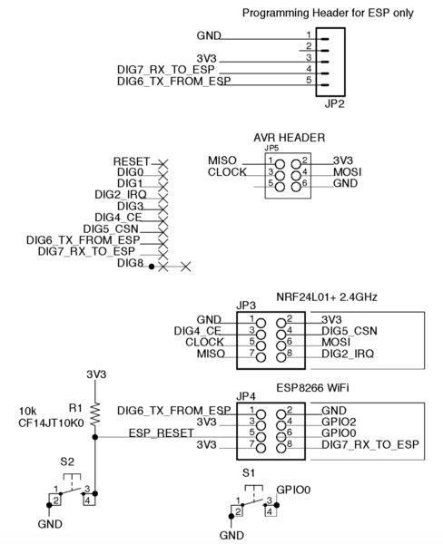
Here's the schematic for reference: | Here's the schematic for reference: | ||
| − | [[File:RFCheaterSCH.png| | + | [[File:RFCheaterSCH.png|488px]] |
== Assembly == | == Assembly == | ||
| Line 14: | Line 21: | ||
The board ships as a bare board like this: | The board ships as a bare board like this: | ||
| − | [[File: | + | [[File:RFCheaterBareBoard.png|150px]] |
| − | |||
| − | |||
| − | |||
| − | |||
| − | |||
| − | |||
| − | |||
| − | |||
| − | |||
| − | |||
| − | |||
| − | |||
| − | |||
| − | |||
| − | |||
| − | |||
| − | |||
| − | |||
| − | |||
| − | |||
| − | |||
| − | |||
| − | |||
| − | |||
| − | |||
| − | |||
| − | |||
| − | |||
| − | |||
| − | |||
| − | |||
| − | |||
| − | |||
| − | |||
| − | |||
| − | |||
| − | |||
| − | |||
| − | |||
| − | |||
| − | |||
| − | |||
| − | |||
| − | |||
| − | |||
| − | |||
| − | |||
| − | |||
| − | |||
| − | |||
| − | |||
| − | |||
| − | |||
| − | |||
| − | |||
| − | |||
| − | |||
| − | |||
| − | |||
| − | |||
| − | |||
| − | |||
| − | |||
| − | |||
| − | |||
| − | |||
| − | |||
| − | |||
| − | |||
| − | |||
| − | |||
| − | |||
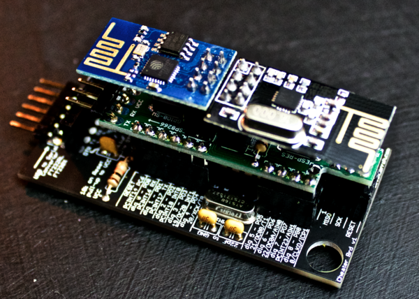
| − | The | + | The board can be assembled easily, since it only consists of through hole components, then it looks like this, then with the Radio Modules installed as mounted on the Cheater Board: |
| − | [[File: | + | [[File:RFCheaterAssy.png|150px]] [[File:RFCheaterAngleView.png|600px]] |
| − | + | === Parts === | |
| − | + | It is up to you to order the parts. The list can be downloaded [http://www.kevindarrah.com/wp-content/uploads/2016/04/RFCheater_v2_BOM.xlsx **HERE**]. This can be directly uploaded into [https://www.digikey.com Digikey] if you'd like. The parts are pretty self explanatory - make sure that you pay attention to which way the Radio Modules plug into the board. There are markings/text on the board indicating which header each module should be used for. | |
| − | |||
| − | |||
| − | |||
| − | |||
| − | |||
| − | |||
| − | + | == Pin Out == | |
| + | ESP8266: | ||
| + | * TX from the ESP8266 goes to Arduino Pin 6 - pin 6 would be a Software Serial RX | ||
| + | * RX to the ESP8266 comes from Arduino Pin 7 - pin 7 would be a Software Serial TX | ||
| + | * GPIO 2 is not connected | ||
| + | * GPIO 0 is connected to one of the pushbuttons (under the ESP8266) pulled LOW when pressed - floating when not pressed | ||
| + | * RESET is connected to the other pushbutton (under the NRF24L01+) pulled LOW when pressed | ||
| − | + | NRF24L01+: | |
| + | * IRQ is connected to Arduino Pin 2 - Interrupt 0 | ||
| + | * CE is connected to Arduino Pin 4 | ||
| + | * CSN is connected to Arduino Pin 5 | ||
| + | * CLOCK is connected to Arduino Pin 13 | ||
| + | * MOSI is connected to Arduino Pin 11 | ||
| + | * MISO is connected to Arduino Pin 12 | ||
| + | * Note that Arduino Pin 10 will not be useable, since the NRF24L01+ communicates via SPI, thus making the SS (Slave Select) pin not useable - there may be workarounds for this. | ||
| − | + | == Test Code == | |
| + | Coming soon! | ||
Latest revision as of 14:11, 4 April 2016
Introduction
The RF Cheater Board is a simple breakout board for the (NRF24L01+ 2.4GHz Transceiver Module) and (ESP8266 WiFi Module). The board was designed to plug right on top of the Cheater Board
Features of the board:
- Supports the low cost WiFi module ESP-01. Search for ESP-01 in eBay or Amazon. I have seen these go for as low as $3USD
- Supports the NRF24L01+ 2.4GHz Wireless Transceiver. Great for point-point or local mesh networks. See pictures below for reference to which module is supported.
- Interface pins for both NRF24L01+ and ESP8266 routed to ATMEGA328, to allow for communication with the your local network of 'things' and then out to the 'cloud' via WiFi
- Standalone 'bare metal' programming of the ESP8266 via a header USB-Serial interface. Pushbuttons connected to allow for programming modes of the ESP8266.
- Board runs at 3.3V only! be sure to run the Cheater board at 3.3V, since there are no level shifters between the radio modules and the ATMEGA328 microcontroller.
Here's the schematic for reference:
Assembly
The board ships as a bare board like this:
The board can be assembled easily, since it only consists of through hole components, then it looks like this, then with the Radio Modules installed as mounted on the Cheater Board:
Parts
It is up to you to order the parts. The list can be downloaded **HERE**. This can be directly uploaded into Digikey if you'd like. The parts are pretty self explanatory - make sure that you pay attention to which way the Radio Modules plug into the board. There are markings/text on the board indicating which header each module should be used for.
Pin Out
ESP8266:
- TX from the ESP8266 goes to Arduino Pin 6 - pin 6 would be a Software Serial RX
- RX to the ESP8266 comes from Arduino Pin 7 - pin 7 would be a Software Serial TX
- GPIO 2 is not connected
- GPIO 0 is connected to one of the pushbuttons (under the ESP8266) pulled LOW when pressed - floating when not pressed
- RESET is connected to the other pushbutton (under the NRF24L01+) pulled LOW when pressed
NRF24L01+:
- IRQ is connected to Arduino Pin 2 - Interrupt 0
- CE is connected to Arduino Pin 4
- CSN is connected to Arduino Pin 5
- CLOCK is connected to Arduino Pin 13
- MOSI is connected to Arduino Pin 11
- MISO is connected to Arduino Pin 12
- Note that Arduino Pin 10 will not be useable, since the NRF24L01+ communicates via SPI, thus making the SS (Slave Select) pin not useable - there may be workarounds for this.
Test Code
Coming soon!


