Difference between revisions of "The Ultimate Prototyping Board:"
| Line 34: | Line 34: | ||
[[File:protoV2_playground.png|800px]] | [[File:protoV2_playground.png|800px]] | ||
| + | The connections on the board are similar to how a bread board works. The red lines on the image above show how the through-holes are tied together. Silk screen on both sides of the board also make this clear. Vsys (System Voltage) and GND (Ground) rails run up and down the board for easy access. There is also an 'other voltage' rail that runs along the upper and lower sections of the board that can be used as an auxiliary voltage in the circuit. | ||
| + | ===Power=== | ||
== Assembly == | == Assembly == | ||
Revision as of 17:51, 21 April 2016
Contents
Introduction
This is the second version of the Ultimate Prototype Board. Information about the first version can be found HERE
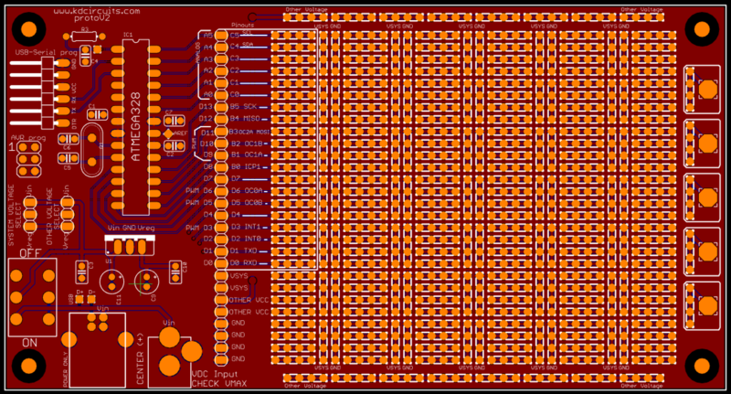
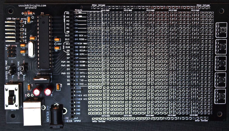
The Ultimate Prototype Board offers a slick solution to making your projects more permanent. Instead of clearing off your breadboard to make room for a new project, you can use this board to keep your projects forever! The board takes care of the Microcontroller and supporting circuitry for you as well as the programming headers, power entry, mounting holes, and clear labeling. Then you have the 'playground' section for your custom circuitry that you can solder directly to the board.
Features of the board:
- ATMEAG328 Microcontroller (28 pin Through Hole) support + Crystal/Caps
- AVR Programming Header
- Arduino Compatible Programming Header (USB-SERIAL)
- USB Power Input OR Barrel Jack Power
- Linear Voltage Regulator to Step voltage down for your projects
- Power Selection Jumpers - Choose where the microcontroller gets its power from Input Voltage or Regulated Voltage (see below)
- Power Switch
- x4 Mounting Holes (1/8")
- Board Dimensions 6"x3.2"
Purchase
The board is available through MKLEC
How it Works
Proto Area
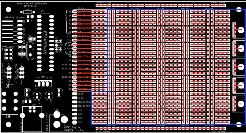
The area in blue here is the proto area for your custom circuitry.

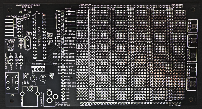
The connections on the board are similar to how a bread board works. The red lines on the image above show how the through-holes are tied together. Silk screen on both sides of the board also make this clear. Vsys (System Voltage) and GND (Ground) rails run up and down the board for easy access. There is also an 'other voltage' rail that runs along the upper and lower sections of the board that can be used as an auxiliary voltage in the circuit.
Power
Assembly
The board ships as a bare board (component kits may be available as well), but here is the complete list of COMPONENTS that you can order straight from Digikey.

Testing & Programming
Tutorial on Burning the Arduino Compatible Bootloader:

