Difference between revisions of "Pusher"
From Kevin Darrah Wiki
| Line 3: | Line 3: | ||
[[File:Screen Shot 2017-06-04 at 1.38.08 PM.png|600px]] | [[File:Screen Shot 2017-06-04 at 1.38.08 PM.png|600px]] | ||
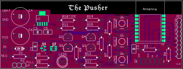
| − | + | The Pusher Board is an IoT project that does one thing - it pushes you a notification triggered by a digital input. Well, it's much more than that, but this is the inspiration. I wanted to design a WiFi board that essentially sleeps most of its life, but when that door switch, flood sensor, motion sensor, etc.. gets triggered, I just want a notification immediately on my phone. And that's about it... a perfect IoT device in the background doing its job. | |
= Version 1 = | = Version 1 = | ||
| − | Very first | + | Very first prototype board |
| + | * Mostly through hole components for easy testing and assembly | ||
| + | * ESP8266 based (ESP-12S module) | ||
| + | * Wake on regular timer interval - set for 1hr during my testing. | ||
| + | * Wake on Digital Input - Normally Closed type contact, so works nicely with door sensors. | ||
| + | * Tested sleep current <1uA that's years and years of battery life. | ||
| + | * Max Battery Voltage is ~4.2VDC, so designed to be used with standard Lithium Batteries. | ||
| + | * <span style="color:red">Note: this board does re-work in order to exercise all of the functionality. Please watch assembly videos below for detailed information</span> | ||
== Schematic == | == Schematic == | ||
| − | |||
| − | |||
| − | |||
| − | |||
== Purchase == | == Purchase == | ||
| Line 19: | Line 22: | ||
== Parts == | == Parts == | ||
| − | |||
== Assembly == | == Assembly == | ||
| Line 25: | Line 27: | ||
== Tutorials == | == Tutorials == | ||
| − | |||
| − | |||
| − | |||
| − | |||
| − | |||
| − | |||
| − | |||
| − | |||
| − | |||
| − | |||
| − | |||
| − | |||
| − | |||
| − | |||
| − | |||
| − | |||
Revision as of 21:27, 27 June 2017
...Back to Projects:
The Pusher Board is an IoT project that does one thing - it pushes you a notification triggered by a digital input. Well, it's much more than that, but this is the inspiration. I wanted to design a WiFi board that essentially sleeps most of its life, but when that door switch, flood sensor, motion sensor, etc.. gets triggered, I just want a notification immediately on my phone. And that's about it... a perfect IoT device in the background doing its job.
Version 1
Very first prototype board
- Mostly through hole components for easy testing and assembly
- ESP8266 based (ESP-12S module)
- Wake on regular timer interval - set for 1hr during my testing.
- Wake on Digital Input - Normally Closed type contact, so works nicely with door sensors.
- Tested sleep current <1uA that's years and years of battery life.
- Max Battery Voltage is ~4.2VDC, so designed to be used with standard Lithium Batteries.
- Note: this board does re-work in order to exercise all of the functionality. Please watch assembly videos below for detailed information
Schematic
Purchase
given to Patrons ...
Parts
Assembly
Coming Soon...
