CollectorBoard
...Back to Projects:
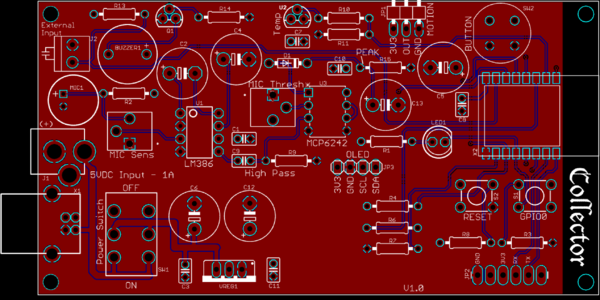
The Collector board was originally designed to work with the Pusher - basically a board that can "Listen" for push notifications. This is especially useful for situations when notifications are disabled on the smart phone (Do Not Disturb mode at night). In addition to receiving push notifications, it also interfaces to sensors that benefit from an 'always on' power source, such as Smoke Alarm detection, motion sensors, etc... The board is based on the ESP8266 WiFi module, so it can also be used as a development board for other projects.
Version 1
- All through-hole components except ESP-12S WiFi Module
- USB B or Barrel Jack for 5VDC power input with Power Switch
- Microphone Circuit to detect smoke alarms (made a video on this recently)
- Header to mount PIR Motion Sensor
- TMP36 Temperature Sensor
- External Input - could monitor a door/window if you want
- Header to mount OLED display
- Buzzer
- Silence Button - in case you want to mute all activity on the board.
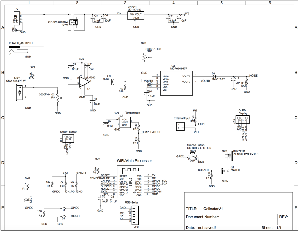
Schematic
Purchase
given to Patrons
Parts
Parts List can be downloaded HERE
There are headers on the board to pair up with common modules, but please make sure the pinout matches.
- The OLED Display that has been tested with the board is the 0.96" 128x64 and uses Arduino Libraries for the SSD1306 driver using I2C. The display tested was purchased HERE.
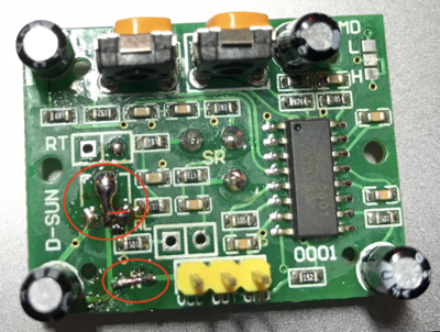
- The Motion Sensor pinout seems to vary, so make sure it is VCC-OUT-GND. It turns out a lot of these modules only support a 5V input, so I modified the one I had to work with 3.3V.
I removed the diode and shorted it out with a piece of wire. Then I removed the voltage regulator and shorted the Input to the Output. This has been working pretty well so far:
Assembly
The assembly is pretty much a straight forward effort - everything is through hole except for the ESP-12S module. I think it would be easier to solder this part in first, so you don't have the large pushbutton in the way of your iron.
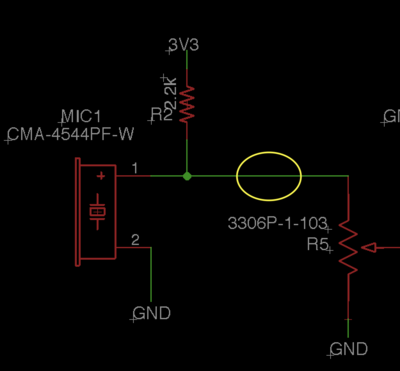
Only re-work needed is to add a capacitor
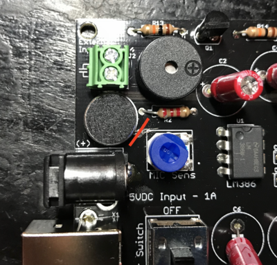
So first need to cut this trace:
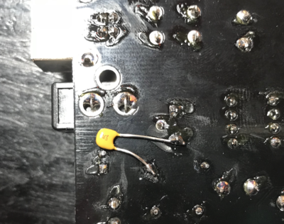
Then add a 0.1uF capacitor here - I added it on the bottom side:
