TrigBoardPressure
...Back to Projects:
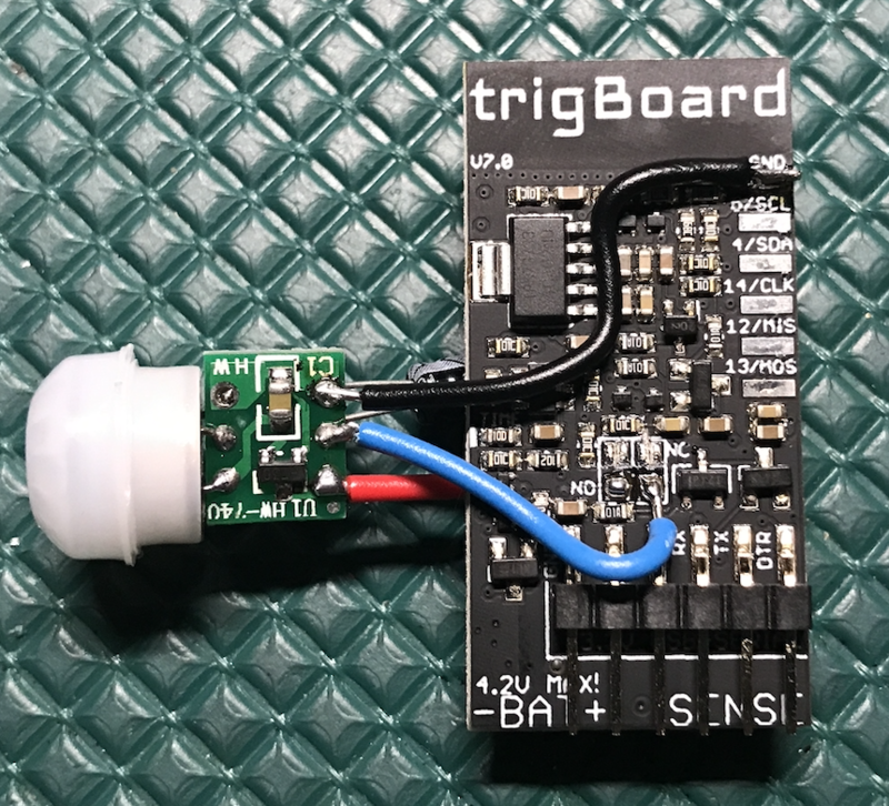
Low power PIR sensors can be tricky to get right - here's a way to get a push notification any time motion is detected. Since the trigBoard uses less than 1uA of standby current, we need to find a PIR sensor that uses very little current, especially because these sensors need to be "always on". I found one that pulls 10-12uA, so this is a perfect fit for this... plus they're pretty inexpensive. That amount current is still low, so with a 1000mAh battery or so, you can expect very long battery life.
Tutorial
UPDATE 1/24/19 after a few days of testing, I'm not a huge fan of these PIR modules. I get quite a few false-positives... like it just goes off on its own with nobody around. The other thing I noticed is that it can be sensitive to RF radiation. I extended the wires out to about 12" or so and that seems to help a lot. Before, I noticed every once and a while it would end up in a never-ending cycle sending notifications. Stay tuned... I'm going to continue to try other PIR sensors.
Parts needed
- PIR Sensor based on the AM312: https://www.amazon.com/gp/product/B07GJDJV63/ref=ppx_yo_dt_b_asin_title_o00__o00_s00?ie=UTF8&psc=1
- 1uF capacitor - any would work that you have lying around.
- trigBoard & battery
Installation
trigBoard Setup
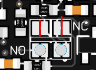
Cut the top "NC" jumpers as well as the small trace under above the jumper to the right. Also, fill in the bottom "NO" jumpers with solder. BE CAREFUL cutting the jumpers! It is very easy to slip with the blade and cut more traces than you intended.
PIR Setup
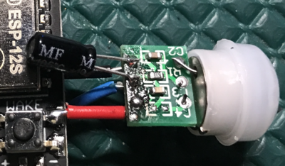
The PIR Sensor will need a 1uF capacitor soldered across the Output to GND - check polarity and make sure the capacitor's negative lead connects to ground:
Wiring
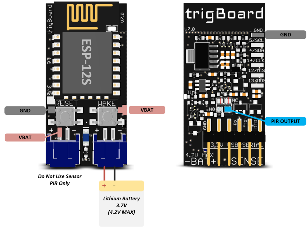
The PIR sensor has three pins:
+ goes to VBAT
- goes to GND
Out goes to PIR Output
You can choose the locations that are easiest to connect to:


